The text read off it
[03.03.01]
03.03 Loader Output
A. Program for Execution
The binary object program deck, together with required subroutines, appropriate I/O routines and tables and a portion of the Basic Monitor, is placed in core storage by the Loader. If the program is to be executed, control is transferred to it at the conclusion of the loading process. The following chart illustrates the general layout of core storage at execution time.
| Address | Core storage region |
|---|---|
| 32767 | (top of core) |
| 32256 | Available for Customer Usage |
| Primary Object Time Subroutines | |
| Program Initialization and Loading Routines (Overlaid by buffer pools) | |
| Buffer Pools | |
| Secondary Object Time Subroutines | |
| Program | |
| Transfer to Program Start | |
| Define, Attach Calling Sequences | |
| File Lists | |
| 3840 | File Block |
| 1856 | IOBS |
| 1400 | CTM (Commercial Translator Monitor) |
| 350 | IOEX |
| 0 | Basic Monitor |
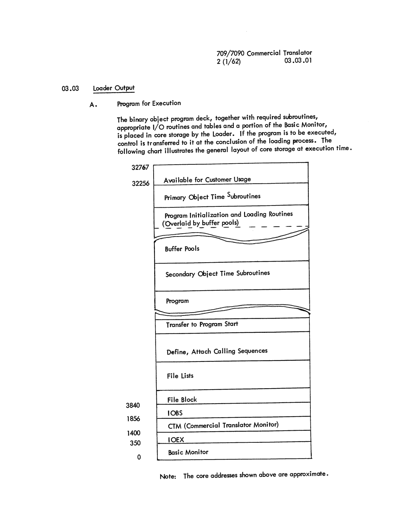 General layout of core storage at execution time (page 03.03.01).
Note: The core addresses shown above are approximate.